Your Cart is Empty
DESIGNED IN SEATTLE | MADE IN SEATTLE
DESIGNED IN SEATTLE | MADE IN SEATTLE

03 - FOAM PLUG MACHINING
January 06, 2020 4 min read
As previously explained in our article Plug & Mold Design, building a plug is one of the first steps towards making a mold for composite parts. A plug looks like the final part we want to make, and it’s used to give the mold it’s shape. Sometimes we can use an existing part as a plug – this is called making a “splash plug”, which we talk more about in our articleSplash Plug Fabrication. But what if we need to make a plug for a brand-new part that no one’s ever made before, or what if we only have a 3D model of the part? In these scenarios we must fabricate a plug!
Choosing the Right Machine
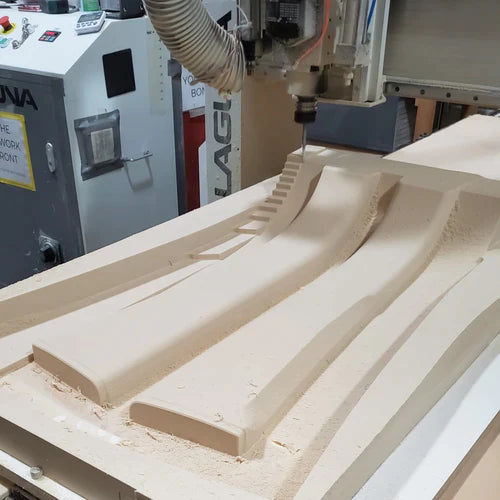
When it comes to making a plug for composites, you do have a few options. The most basic option is to hand shape a plug from foam, wood, or clay. This hand process was the primary option until machines like CNC’s and 3D printers came about. CNC machining allows us to fabricate a very accurate plug from a 3D CAD model at a large scale. 3D printers work great as well but are often limited in size. Here at the Common Fibers shop, we us a Laguna SmartShop II 3-axis CNC router with a 4’x8’ bed to produce most of our plugs. Any large format router or CNC will work, but as they say, you get what you pay for! If you need high tolerances, you will need a costlier machine like a HAAS.
Any large format router or CNC will work
Plug Material Options
A plug can be machine from a large variety of materials. High end plugs may be made from steel, aluminum, or even Invar! Plugs made from metals are often intended for making multiple molds for high rate production of precision parts. In most cases, it makes more sense to make a plug from wood or foam. We make our plugs out of high-density polyurethane foam made specially for machining, called tooling board.For most applications we useGeneral Plastics’ FR-4515 tooling board. FR-4515 is a good compromise between low cost and good material properties (density and temperature resistance, for example). Lower density foams can be cheaper, but we recommend against choosing foam with a density lower than 10lbs as it doesn’t machine as nicely and is easy to damage during the mold-making process. You can learn more about the FR-4500 series and other types of tooling board, including machining guidelines, on General Plastic’s website here:https://www.generalplastics.com/. We typically avoid making plugs from wood like MDF as it dulls the CNC bits and is harder to work with.
For most applications we use high density 15 lb foam.
Setup
After we choose our foam, the next step is to cut it down to roughly the size of our plug and “fixture” it to the CNC bed. It’s very important to do a good job fixturing the foam to the bed, otherwise it can move during machining and ruin an expensive piece of foam (a 4’x8’x6” piece of foam is close to $1,000!). Our machine has a series of vacuum holes in the bed that allow us fixture parts with suction, and we’ll also often use wide strips of double-sided carpet tape on the bottom of the foam to keep it from moving. In some situations, you may need to find other ways of fixturing the foam such as with clamps and vices.
It’s very important to do a good job fixturing.
Tool Selection
Next, we need to decide which mill tools to use. There are thousands of different CNC bits available. Do not get lost looking for the perfect tool! Foam is very forgiving and almost any tool will work. For most foam machining we rely on just two or three tools. For removing lots of material as quickly as possible, we use a roughing mill such as this 6” long by 1” diameter square end mill:https://www.mcmaster.com/8819a47. We can run a bit this size at around 150 inches per minute. We follow with a ½” or ¼” diameter ball end mill for high speed surface milling. This process takes very small step-overs and therefore can be run as fast as the machine will go (~300 in/min). Depending on the complexity of the part and the size of the internal radii, it may be necessary to run a final 1/8” ball end mill to clean up the final details.
Foam is very forgiving and almost any tool will work.
CAM
Before our mill tools can be put to the task of machining the plug, we need to create a program for the CNC machine to follow. We use Autodesk Fusion 360 CAM (Computer-Aided Manufacturing) software to import a 3D model of our plug and choose from several different operations to create “toolpaths” for our machine. We use different machining strategies depending on the shape of the plug and other factors such as the required finish quality. There are four most commonly used toolpaths required for machining a plug. Start with a simple clearing operation or “Roughing Pocket”. With most of the material removed, we follow with either “Parallel” or “Contour” passes. Contour passes are required only if there are areas with steep walls. If radii need to be cleaned up at the end, we may run a “Pencil” pass. After we are satisfied with the toolpaths we have created in CAM, we use a “post-processor” to translate the CAM into “G-Code”, which is a set of instructions that the CNC machine can understand.
The four most commonly used toolpaths are roughing pockets, parallels, contours, and pencils.
Once we have our program written and loaded on the CNC machine, all that’s left is to press start, kick back, and watch the machine sculpt a beautiful plug! Well, truthfully there are many more intricacies to understand, rabbit-holes to fall down, and pitfalls to avoid when machining plugs that we haven’t covered here. Feel free to reach out to our pros with specific questions about the process, and read our other blogs in this series to learn more about fabricating strong, light, and beautiful carbon fiber parts! Our soon to be Troubleshooting Blog will covers some of the finer details of this process.
Subscribe
Sign up to get the latest on sales, new releases and more …